000011.1 General
000011.1.1 Application
The requirements of this chapter and 26.7 shall apply to non-metallic enclosures and non-metallic enclosures of enclosures in relation to type of protection.
00001 Note 1: Some examples of non-metallic parts of enclosures related to the type of protection against explosion include: seals of type "e" or type "tD" enclosures, fillers of type "d" or type "e" cable entries, Seals for cable entry devices, seals for "e" type switch actuators, etc.
The requirements of 7.4 also apply to the non-metallic parts of the outer surface of the enclosure.
00002 Note 2: Non-metallic coatings, films, foils and sheets are usually attached to the outer surface of the enclosure to provide additional environmental protection. This chapter deals with their ability to accumulate electrostatic charges.
000011.1.2 Material requirements
Documents specified in Chapter 24 should describe the material of the housing or housing part.
000011.1.3 Plastic material
The technical requirements for plastic materials should include the following:
a) the name of the manufacturer;
b) accurate and complete data including color, percentage of fillers and other additives (if used);
c) Possible surface treatments such as varnishing;
d) The temperature index TI corresponding to the point 20000h of the thermal stability curve, measured at this point in accordance with GB/T 11026.1-2003, GB/T 11026.2-2000 and GB/T 9341-2000, has a bending strength reduction not exceeding 50%. If the material is not broken before the heat radiation, the temperature index shall be determined in accordance with the tensile strength determined by the IA or IB test bars specified in the GB/T 1040.2-2006 standard. Relative Heat Index (RTI-Mechanical Shock) TI may be replaced by a value determined by ANSI/UL746B.
Values ​​for determining the above characteristics should be provided.
00001 Note: This section does not specify the need to verify that the plastic material meets the manufacturer's specifications.
000011.1.4 Elastic materials
Technical requirements for elastic materials should include the following:
a) the name of the manufacturer;
b) Accurate and complete data including color, percentage of filler and other additives (if used);
c) Possible surface treatments such as varnishing;
d) Continuous operating temperature (COT). The relative heat index (RTI-mechanical shock) may be determined in accordance with ANSI/UL746B instead of COT.
Values ​​for determining the above characteristics should be provided.
00002 Note: This section does not specify the need to verify that the material of the elastomer meets the manufacturer's specifications.
000011.2 Thermal stability
000011.2.1 Thermal stability test
Heat resistance test and cold resistance test should be carried out in accordance with 26.8 and 26.9.
000011.2.2 Select material
When used under the highest ambient temperature conditions, the temperature index TI or RTI (mechanical shock) of the plastic material corresponding to 20000h point should be at least 20K higher than the temperature of the hottest point of the plastic housing or the plastic part of the housing (see 26.5.1).
The lower limit of the continuous operating temperature (COT) of the elastomeric material should be lower than or equal to the minimum operating temperature, which is at least 20 K higher than the maximum operating temperature.
000011.3 Lightfastness
The light resistance of non-metallic enclosures or non-metallic parts of enclosures should meet the requirements (see 26.10).
If there is no protection against light exposure, the enclosure or enclosure parts made of non-metallic materials associated with the type of protection against explosions shall be subjected to a UV-resistant light test. For Class I electrical equipment, this test is only performed for the luminaire.
If the equipment is installed and installed with measures against sunlight (such as sunlight or lighting), this test is not required, but the equipment should be marked with the symbol “X†in accordance with item 29.2 e), indicating that it has special conditions of use.
00003 Note: It is generally considered that glass and ceramics are not affected by the light test and this test may not be performed.
000011.4 Electrostatic charges on the surface of non-metallic materials
000011.4.1 Applicability
The requirements of this clause apply only to the outer surface of non-metallic materials of electrical equipment.
000011.4.2 Avoid Electrostatic Charge Accumulation on Class I or Class II Electrical Equipment
Electrical equipment should be designed to avoid the risk of ignition caused by electrostatic charges during normal use, maintenance and cleaning. This requirement should be met by one of the following requirements:
a) Reasonably select materials so that the surface insulation resistance measured according to 26.13 is not more than 109Ω;
b) define the surface area of ​​non-metallic parts of the enclosure, as shown in Table 6;
The surface area is defined as follows:
00001 â— For sheet materials, the area should be exposed (electrical) area;
00002 â— For curved objects, this area should be the projected part of the object given the largest area;
00003 â— For stand-alone non-metallic parts, if they are enclosed by a grounded metal frame, the area should be assessed separately;
00003 Note 1: If the exposed area of ​​non-metallic material is surrounded by a grounding frame, the surface area can be increased by a factor of four.
Alternatively, for long components with non-metallic surfaces, such as pipes, rods, or ropes, the surface need not be considered, but their diameter and width should not exceed the values ​​in Table 7. Cables connected to external circuits do not fall within the scope of this requirement. See 16.6.
c) limit the non-metallic layer coated on the conductor surface, the thickness of non-metallic layer should not exceed the value of Table 8;
d) For the limitation of the transferable charge, test using the method specified in 26.14;
e) Capacitance measurements cannot store hazardous charges when tested in accordance with the test methods specified in 26.15;
f) Measures using a conductive coating. Non-metallic surfaces can be covered with a strong, conductive coating. The resistance between the coating and the bonding point should not exceed 109Ω. The resistance shall be measured in accordance with 26.13, but a 100 mm2 electrode shall be used to measure the most unfavourable position between the surface and the bonding point. The equipment shall be marked with the symbol "X" in accordance with the requirements of item 29.2 e), and shall provide in the document guidelines for the use of equipotential bonding and information for the user to determine the durability of the coating material to environmental conditions.
g) For the electrical equipment to be used for fixed installations, precautionary measures against the danger of electrostatic discharge can be a factor to consider when installing the equipment or elements of the equipment installation process. In this case, the equipment should be marked with an “X†in item 29.2 e) and provide the necessary information in the document to ensure that the risk of electrostatic discharge of the equipment is minimized. If applicable, the device shall also be provided with an electrostatic charge warning plate in accordance with 29.11 g).
00004 Note 2: The use of warning signs should be used with caution to control the danger of electrostatic sparks. In many industrial applications, especially coal mines, warning signs may be difficult to identify due to coal dust heaps. If there are dust accumulations on the warning signs, cleaning the warning signs may result in electrostatic discharge.
00005 Note 3: When selecting an electrically insulating material, consideration should be given to maintaining a minimum insulation resistance in order to prevent discharge of exposed non-metallic parts in contact with live parts.
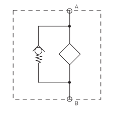
SDRF filter consists of a Filter Housing with a screw-on cover plate.There is a clogging indicator port on the cover plate.

Filter Element
Filter elements are available with the following pressure stability values:
BN/HC: 25 bar
Paper(P/HC): 10 bar
Wire mesh( W/HC ): 30 bar
Stainless steel fiber( V ): 30 bar
General
Mounting
Oil tank-top or inline mounting
Flow
Inlet: side Outlet: down
Temperature range
-10℃~100℃ (others on request)
Bypass cracking pressure
â–³Po=3bar+0.5bar (others on request)
Compatibility
It can be used for mineral oils, lubrication oils, non-flame fluids,synthetic and rapidly biodegradable fluids. For water or other application, please contact us.
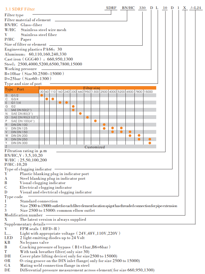
Model code

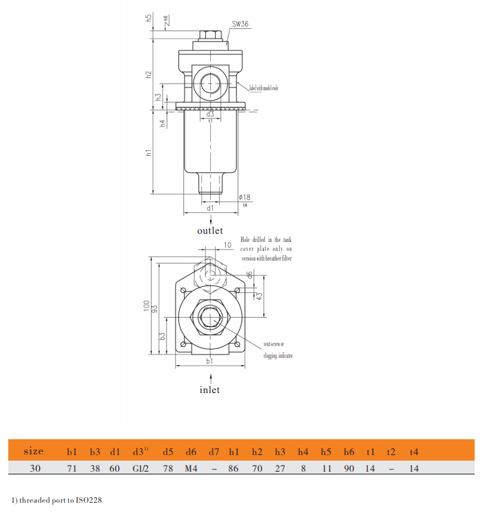
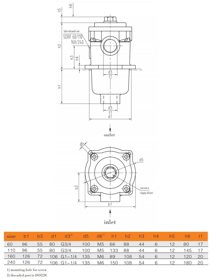
Filter dimension


