How to do the wiring of weak network engineering network room? Can we better manage the construction? Today, we will focus on the wiring specifications of the network equipment room and introduce the graphic.
I. Overview
With the continuous development of the business, IDC is getting bigger and bigger. In order to improve the delivery time and efficiency of IDC's new network equipment, the optical fiber and network cable deployment in the equipment room are put forward higher requirements and standards. The document is summarized and more in line with the current IDC network equipment wiring specification operation and acceptance criteria. Specific solutions in terms of aspects.
The purpose of this document is to guide service providers in the network equipment fiber and network cable deployment, power bundles can be more standard, more standardized, unified network construction wiring acceptance criteria.
Second, the term explanation and interconnection instructions
Computer room network interconnection topology:
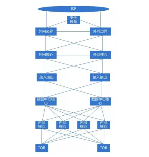
TOR: Intranet access switch, 1U box network equipment, equipped with 48 10G optical ports and 4 40G optical ports; 10G optical ports use AOC cables to connect servers 10 Gigabit ports, 40G optical ports are connected to MPO fibers to The core of the intranet of the equipment room, a single TOR covers the servers of two cabinets;
ILO: Server ILO access switch, also known as management network access switch, 1U box network equipment, equipped with 48 10/100/1000M adaptive electrical ports and 1 1/10G optical port, 48 electrical ports down the server Gigabit Ethernet port and network device MGMT port; optical port is connected to the core of the computer room management network with 10G multimode fiber, and a single ILO covers two cabinets of servers and network devices;
Core of the internal network: network core equipment, frame network equipment, equipped with multiple 40G optical ports and 10G optical ports, etc. (depending on the configuration), 40G optical ports are connected to the TOR in the equipment room through MPO fibers, and the 40G optical ports pass through the MPO optical fibers. Linked to the core equipment of the computer room data center;
Data center core: network core equipment, frame network equipment, equipped with multiple 40G optical ports and 10G optical ports (specifically, configuration), 40G optical ports are connected to the internal network core through MOP fiber, and 10G optical ports pass 10G single mode. Optical fiber connection transmission (dedicated line), 10G optical port is connected to the access device through 10G multimode fiber connection;
Uniform access and output device: similar to a NAT translation device, used to convert between public and private network addresses. A single device is equipped with multiple 10G optical ports. The 10G optical port is connected to the data center core through multimode fiber. Core; additionally connected to the session synchronization switch through 10G multimode fiber for session synchronization between different devices;
External network core: The core network equipment in the external network area is equipped with 40G and 10G optical ports. The 10G optical port is connected to the unified access and access, the external network access of the independent external network area, and the security device through the multimode optical fiber. The 40G optical port passes. MPO fiber uplink network boundary;
External network boundary: Network equipment connected to the ISP, with 40G and 10G optical ports. The 10G optical port is connected to the ISP device through the single-mode fiber. The other 10G optical port is connected to the security device through the multimode fiber. The 40G optical port is connected through the MPO fiber. External network core;
10G-AOC cable: Similar to the fiber of the optical fiber, the optical module is integrated at both ends for the connection between the TOR switch and the server 10G network port;
Management network cable: Category 6 or Category 6 copper cable, RJ45 connector, used for connection between ILO access switch and server Gigabit Ethernet port and network device MGMT port;
Third, the wiring rules in the equipment room
The same IDC, the same specification rack, the wiring method should be consistent, which is convenient for daily operation and maintenance. Network equipment such as core network equipment, internal network access equipment, and management network access equipment should be neatly wired. The optical fiber and network cable should not block the air inlet and outlet of the network equipment. It should not be reserved to the bottom of the rack. The fiber and network cable are too long. The label on the sticker should be clear. The method of inserting the optical fiber and the network cable on the front of the network device should be as consistent as possible. The optical fiber and the network cable are tied together. The power cable and the network cable on the back of the network device are neat and uncluttered. The strong and weak cables are separated and have a sense of overallity.
3.1 Core Equipment Wiring Specifications
IDC core network equipment, especially the core equipment of the internal network, will have more interconnections than TOR, so there will be more optical fibers. The core network equipment fiber deployment must be neat and tidy, and can not be interspersed horizontally and vertically. The beautiful wiring inside the cabinet is one of the key points in the network equipment wiring specification.
The fiber is laid vertically from the left or right side of the device, and the place where it is placed cannot block the air inlet and outlet of the network device. The optical fiber is bundled with a Velcro strap at intervals (note: the strap cannot be fixed with white), but the bundle cannot be too tight and the curvature is not too large, usually between 100 and 130 degrees, usually about 110 degrees (the same below) ), you should be able to release it freely, stick the label, and insert it into the device port, try not to block the label, and leave a certain length of space to facilitate the insertion and removal of the fiber.
3.2 Internal network access wiring specification
The internal network access switch is located at the top of the rack. The MPO fiber of the internal network TOR switch 40G is connected to the inner network core, and the 10G-AOC cable is connected to the server. The 1G or 10G port of the ILO switch is connected to the core of the management network. The Gigabit port is connected to the server. The two cabinets in the equipment room share one internal network TOR and one ILO access switch. The 5 meter cable is used in the cabinet. Eight-8 cables are used in the adjacent cabinets, and approximately 18 servers are placed in each cabinet. Schematic diagram of fiber and network cable deployment:
The cables placed on the internal network access switch are sorted by the cable management device. Each of the four network cables on the cable management device is bundled with a cable tie. Each network cable is marked with a label of the yi and the other end is placed in the rack. Inner tray position. The length of the fiber drop does not need to be too long, and the bending degree should not be too large. The fibers that are labeled and connected to different cores should be distinguished by labels of different colors.
3.3 Bridge wiring specification
The interconnection cables between the network devices in the equipment room need to be routed through the bridge (except in the single cabinet).
As shown in the figure, the optical fiber and the network cable in the bridge are placed separately and neatly, and are bundled at intervals for a certain distance to maintain the appearance.
3.4 Cabling Specifications
Inside the cabinet (ordinary server cabinets), there are mainly intranet AOC cables and ILO management network cables, and power cables. Therefore, the number of cables in a single cabinet is large. Each cable needs to be laid on the inside of the cabinet. As shown below
Different cables are distinguished by different color lines, such as internal network cable: blue, ILO line: gray, power cable: black, and the reserved cable length should not be too long. It can be from one side PDU to the other side PDU. Reserving too long cables will affect the cable. The wiring and bundling requirements between the upper and lower servers are as follows: (Because the network cable has electromagnetic interference, to be strong and weak, the power cable and the network cable should be bundled separately)
3.4 Cable label specification
· Core-intranet TOR tag: Since a single TOR has 4 MPO lines connected to 4 intranet cores respectively, the color of the label is used to distinguish the uplinks to different intranet cores, such as red, yellow, blue, and green. Corresponding to the inner network core 1, 2, 3, 4; the label format is unified with the "cabinet A ~ cabinet B # number of roots" mode, such as XX machine room -02-01 ~ XX machine room-01-08 #1. According to the custom, cabinet A is the core cabinet and cabinet B is the non-core cabinet.
· Special equipment interconnection label: Whether it is interconnection wiring between special network equipment such as network cable or fiber optic fiber, the label is uniformly marked as "rack A~rack B# number one" mode, such as XX machine room -02-08~XX machine room- 01-08#1.
· Internal network access switch-server interconnection label: The front side reflects the rack position and port information of the internal network access switch, and the reverse side reflects the rack position information of the server; for example, the front A1-4-J-17-24-Gi1/1 , reverse J-17-01 (where A1-4 indicates the name of the machine room, J refers to the Jth column, 017 refers to 17 cabinets, 24 indicates the 24th pallet position, and Gi1/1 refers to the switch 1/ 1 port. The reverse side is represented as the rack position of the server);
note:
1. A single cabinet with a height of 48U, one server per 2U space, that is, one tray per 2U, the correspondence from bottom to top is 01, 02, 03, ... 24, etc.
2. Because there are two PDUs in a single cabinet, the two PDUs are named A and B. The power labels are named after letters and numbers. The numbers are in the front and the numbers are in two digits. . For example, 01A-24A, 01B-24B.
Medical Products Assembly Machine:
Medical products assembly machine is generally used to assemble parts of medical products to be one whole set, like Syringe Assembly Machine to assemble syringe barrel, plunger, gasket and ready needle, or Needle Assembly Machine to assemble needle cap, needle hub and cannula.
Advantages of medical products assembly machine:
1. Easy operation
2. Highly automatic
3. High production capacity

If you have any question, please feel free to contact us. Your visit to our factory will also be much welcomed. Looking forward to hearing from you soon!