Hardware Automatic Assembly Equipment Hardware Automatic Assembly Equipment,Hardware Welding Machine,Hardware Welding Equipment,Hardware Automatic Welding Machine Shenzhen Yonglun Intelligent Equipment Technology Co., LTD , https://www.foyooo.com
In theory, the measurement of heat flow rate in steady flow can be attributed to the product of the mass flow of the fluid and its temperature difference and the specific heat of constant pressure, ie: ![]() In the experiment, the direct measurement of the heat flow rate is mainly used. Assuming that the specific heat of the constant pressure of the fluid is constant, it is simplified as the measurement of the mass flow rate and the temperature difference. To measure the heat, the heat flow rate must be continuously measured and accumulated. Summing. The research of this type of metering instrument is of great significance in the fields of heating and ventilation, energy utilization, and experimental research. However, the research and development of such instruments is difficult. Taking the analysis of the central heating system and the heat meter of the central air-conditioning system as an example, there are the following problems: solve;
In the experiment, the direct measurement of the heat flow rate is mainly used. Assuming that the specific heat of the constant pressure of the fluid is constant, it is simplified as the measurement of the mass flow rate and the temperature difference. To measure the heat, the heat flow rate must be continuously measured and accumulated. Summing. The research of this type of metering instrument is of great significance in the fields of heating and ventilation, energy utilization, and experimental research. However, the research and development of such instruments is difficult. Taking the analysis of the central heating system and the heat meter of the central air-conditioning system as an example, there are the following problems: solve;
1 In the heating system, the fluid velocity is low and the mass flow rate is small. How to accurately measure the small flow rate fluid in the heating system is difficult.
The measurement of the inlet and outlet temperature difference must ensure certain accuracy, and at the same time ensure that the temperature difference is synchronized with the measurement of the mass flow rate and store the relevant data; moreover, the temperature (difference) of the system fluctuates greatly, and the actual problems such as the determination and installation of measuring points are more It is extremely difficult to deal with.
3 Even if simultaneous measurement of a small flow velocity heat exchange fluid and a temperature difference can be achieved, the heat flow rate at a time Ï„ can be calculated using the theoretical formula: 
Based on the above issues, to achieve accurate measurement of heat, only by taking full advantage of the combination of software and hardware of the microcomputer, realize a series of functions such as measurement of small flow, small temperature difference, and data storage, calculation, and display. This paper gives full play to the characteristics of easy development, strong functions, small size, and low price for a single-chip microcomputer system. A set of heat meter is developed. The experiment shows that the system has good stability, high precision, strong functions, and high degree of automation. Easy to maintain and other features.
Research and Development In the thermal energy engineering and material science research and production process, the indirect method is usually used to measure the heat. Most of these instruments only measure the heat flow. The current industrial products include radiant heat flow meter and thermal resistance heat flow meter. This type of instrument requires experimental calibration of the instrument constants, there are large errors, measurement lags and other shortcomings, this paper based on the thermal theory of the formula of the discrete equation, based on the full use of MCS51 microcontroller system has the advantages of easy development, hardware and software to achieve The intelligent calculation of heat, combined with the difficulties of heat measurement, enabled the intelligent instrument to achieve the following functions well;
(1) Measurement of temperature difference, this function is completed by two-stage amplifier circuit, A/D conversion circuit and related acquisition software.
(2) The measurement of small flow rate mainly depends on magnetic induction components to convert the flow signal into a standard frequency signal. The MCS51 single-chip microcomputer and related acquisition software can realize the cumulative measurement of the frequency signal.
(3) The cumulative calculation of heat and data storage functions are mainly accomplished by software and corresponding registers.
(4) Power-off protection function, the system will write the important data into the memory and save it due to external power-off. The system-owned power supply will start to work and start recording the power-off start time and the incoming call time. After the call, it will be automatically disconnected. The electrical time is accumulated and stored in the external RAM.
(5) Display function, whether users or heating companies can understand the relevant data information through the display function of the instrument.
(6) Zeroing function: The heating company can clear the instrument at the end of the heating cycle to facilitate management.
In order to realize the above functions of the instrument, the system hardware is mainly composed of the following modules: a basic module consisting of a single-chip microcomputer MCS51 plus an external crystal circuit and a reset circuit, a power supply module, an amplification and A/D conversion module, an external RAM, and a voltage monitoring module , external clock and flow measurement module, keyboard and display module, etc., system components are shown in Figure 1, in which the composition of each module and the main functions are as follows:
The basic module consisting mainly of MCS51 is the core part of the system. It mainly completes the data collected by the system for relevant processing, coordinates the work of other modules, and makes the whole system work in unison. The selected chip is an 8051 type single chip microcomputer. 5 internal interrupts, 4K of ROM program memory, very convenient to use, the external crystal used 12HZ, reset circuit is mainly designed for the easy operation and management of the calorimeter, and the function of the keyboard is connected to the reset key.
System power supply module: It mainly supplies 5V standard DC operating voltage to the system, including the operating voltage of the single-chip microcomputer, operational amplifier, LCD display, and A/D conversion, and the standard comparison voltage, etc. provided by this power supply. The precision of this power supply is The impact of the entire system is enormous, mainly consisting of a transformer, a rectifier circuit, a voltage regulator, and a comparison circuit. The output voltage of the power supply is measured by a 6.5-bit KEITHLEY2000 multimeter and its output range can be stabilized at 4.999-5.0001V. The accuracy is extremely high and the system error caused by the reference voltage is negligible.
Amplification and A/D conversion module: The main function is to complete the amplification of the thermocouple signal and send it to the corresponding register via A/D conversion for related calculations. The accuracy of this module directly affects the temperature measurement accuracy of the system and is the main source of temperature measurement error. Therefore, the selection of amplifier parts mainly considers the precision, the ability to suppress zero drift, and the self-calibration conditions. The chip selected in the system is TLC40502, the error caused by the chip drifting from 5000 times during the debugging process is not more than 0.4°C. Copper thermocouples have a thermoelectric potential of 36μV/°C in the range of 0-100°C, and the error due to zero drift can be less than 0.4°C. The A/D converter selects TLC0831. The operating temperature range of the chip is 0~70°C. It is an 8-bit serial control analog-to-digital converter. It is easy to interface with the microprocessor. The resolution and quantization error of the device are influencing the temperature measurement. The important reason for the accuracy is that the maximum error due to the resolution and quantization error is not more than 0.2°C with the copper-constantan copper thermocouple and the measurement magnification. Therefore, the total temperature measurement error due to amplification and A/D conversion is not greater than 0.6 °C, compared with the design of the general heating system temperature difference of 20 °C, due to the above reasons caused by the maximum error is not greater than 3%, this accuracy is relatively high.
External RAM and voltage monitoring module: External RAM mainly completes the storage of important data, especially when the system is powered off, the collected heat value is stored and the power-down time is memorized for easy management. The main chip is X24C45. The chip is non-volatile and easy to write online. The main functions of the voltage monitoring circuit are: when the main power supply fails, the backup battery is automatically connected to the circuit. When the main power is restored, the backup battery is disconnected to save the system data. The main chip is the INP708. Door-dog timer and μP monitoring circuit for step-down detection.
External clock and flow measurement module: It mainly completes the calculation of the operation time of the single-chip microcomputer, and uses the battery power supply to continue working when the power is off. It provides the clock for recording the power-off time. The main chip is the DSI302, which belongs to the trickle charging time chip, and the flow rate The measuring circuit mainly completes the conversion and measurement of the flow signal. The fluid flow is converted into a frequency signal through the magnetic sensor, optocoupler, etc., and sent to the SCM to record and accumulate to complete the flow measurement. This part is the main source of the error caused by the heat measurement. One of the key is the calibration of the corresponding constants of the frequency signal and flow during the flow signal conversion process, and the effect of the minimum flow rate.
Keyboard and display module: The main functions of the keyboard include clearing, resetting, adjusting the magnification, and querying the register's important immediate value. The display function is to display the calorific value accumulated by the MCU, which is the main source of system power consumption. Select LCD LCD display, with low power consumption, easy to connect with the microcontroller chip CC14544.
(1) In the case of normal power-on operation, the system self-check is performed first, the self-test is completed, and the A/D conversion data is read, converted to the corresponding temperature difference and the frequency value of the counter is read at the same time. The counter resets) and converts it to the corresponding flow value, calculates the heat, reads the cumulative stored calorific value and the measured calorific value from the external RAM, accumulates it, accumulates it, and sends it back to the external RAM memory to complete a measurement cycle.
(2) In the case of abnormal power failure suddenly, the voltage monitoring circuit starts to work, and provides a short-term power supply so that the microcontroller records the values ​​of important data and external clock to the external RAM, and the system begins to record time so that the power supply can return to normal. The system performs the work of (1) and records the cumulative value of the power outage time.
(3) The software automatically measures and eliminates temperature drift and time drift. The zero value of each sensor is set in the software and stored as a data file. The zero value of the corresponding sensor is subtracted from the calorimetric calculation to effectively eliminate the temperature. The influence of drifting and drifting improves the measurement accuracy and overall system accuracy of the sensor.
Accuracy of the experimental calibration and application of calorimeter dimensions 130 × 130 × 40mm, liquid crystal display, to ensure the accuracy of the calorimeter is the key to successful development of the calorimeter or not, therefore, the accuracy of the calibration is an important development and research Content, Fig. 3 is the calibration test bench, the performance of the main surface calorimeter under the small flow conditions performance calibration, the experimental process is as follows: water flow through the 1.5 meter water meter after heating by heating, into the flow transmitter will flow signal The signal is converted into a photoelectric signal and the signal is sent to the heat for counting. The fluid enters the radiator and flows into the standard container after forced convection heat exchange. The temperature measurement points are set before and after the heat sink. In addition to the amplified voltage signal measured by the calorimeter, the 6.5-bit KEITHLEY2000 multi-function meter is used to measure the un-amplified thermocouple output signal. This is used as a check of the temperature difference of the calorimeter. signal. The check of flow is mainly measured by the water meter, flow frequency transmitter, frequency signal and converted into flow. The measured flow value is compared with the value obtained from the standard container and the measurement error is calculated. The experiment mainly focuses on the small flow area. The experimental data is shown in Table 1 (qi in the table represents the flow value). 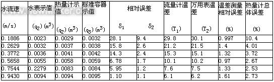
Conclusion In view of the problems existing in the heat process, this article has developed a set of heat metering system to meet the heat measurement of central heating and central air-conditioning systems. It has broad market prospects. The development of this system has succeeded in the market of central heating and central air-conditioning systems. Management is of great significance. The system has the characteristics of high intelligence, stable performance, high precision, complete functions, and easy installation.
(1) The system has the characteristics of small starting flow rate, and the starting flow rate is less than 0.2629m/s, which is smaller than the flow rate started by the water meter. At the normal flow rate, the total error is less than 4%. This accuracy meets the central heating and central air conditioning system. The accuracy of the hot (cold) metering requirement.
(2) The system makes full use of the features of the SCM that is easy to develop, makes full use of its powerful software processing and data acquisition and computing capabilities, realizes the functions that can not be realized by purely mechanical systems, and achieves intelligent requirements such as automatic recording, processing, and displaying data. Automatic correction of temperature measurement errors and other functions, reducing hardware costs, is conducive to market-oriented.
(3) External ROM, power supply monitoring, and external clock and power supply settings enable the SCM system to be used in combination with internal and external resources. In the event of a power outage, the system is automatically transferred to the time, which provides great management for centralized heating and central air conditioning. Convenience, data storage, and other functions have been enhanced and fully automated.
(4) The system also has a few running parts, long service life, low power consumption, easy maintenance and modification, can meet different flow measurement range, easy to form a series of production, while having stable operation, good reproducibility and other characteristics .
References 1 Lu Chongde. Jiang Xuezhi. Yang Xianyong et al. Measurement and processing of thermal parameters. Beijing; Tsinghua University Press. 1990
Wang Furui. Wang Chunyan. Lu Pei et al. Design of a single-chip computer monitoring and control system. Beijing; Beijing University of Aeronautics and Astronautics Press. 1999
3 Wuhan Liyuan Electronic Device User Manual. Wuhan; Wuhan Liyuan Electronics Co., Ltd. 2000
4ModeI2000MuItimeterUser'SmanuaI,Ohio,UsA,KeithIeyInstruments,Inc.1999
Research on Central Heating and Calorimeters for Central Air Conditioning Systems
Key words: Central heating, central air-conditioning system, calorimeter Introduction In the process of central heating and central air-conditioning use charging, it is still calculated according to the building area. This method is no longer adapted to the requirements of market-oriented management, and it urgently needs the heat consumed by users ( The amount of cold is measured accordingly to maintain the interests of both the user and the heating (cold), but no extensive use of similar instruments is currently available. This is due to the difficulty of heat metering, which limits the development of such instruments and development. First of all, because heat is a process quantity, in the experiment or engineering measurement, the traditional measurement method has difficulty in measuring the process quantity itself, and there are problems such as large measurement error and many correction factors. In fact, the traditional measurement method can not meet the accurate measurement of heat, but with the wide application of computer and signal processing technology in the measurement of thermal parameters, the thermal measurement instrument develops intelligently and miniaturizedly and makes full use of the microcomputer software. The combination of hardware enables the accurate measurement of heat. It is also extremely difficult to use the traditional measurement method to complete the cumulative measurement of the above formula. From the data in the table, it can be seen that as the flow rate increases, the flow value measured by either the water meter or the calorimeter becomes more and more accurate, and there is a minimum flow for the calorimeter and the water meter, but the start of the calorimeter is started. The flow rate is smaller than the start-up flow rate of the water meter. The analysis suggests that: The main reason is that the starting resistance of the calorimeter is much smaller than the water meter. After the calorimeter flow rate is greater than the start-up flow rate, the total error is less than 4%. This accuracy meets the accuracy requirements of the central heating system and central air-conditioning system for measuring the amount of heat (cold). Figure 4 reveals the relative error of the water meter and the calorimeter measurement, as can be seen from the figure; the start-up flow rate of the calorimeter is small, the relative error of the measurement is decreasing as the flow rate increases, and the flow rate is greater than 0.9 m/s. The relative error of the water meter measurement is less than the relative error of the calorimeter measurement. This is related to the source of the measurement error. After the calorimeter working flow velocity is greater than the start flow velocity, the error mainly comes from the error of the flow transmitter and the temperature measurement, and is basically constant. However, the overall relative error is not more than 4%. The experimental results show that the system meets the design requirements.
Table 1 Flowmeter calibration test data sheet