Fan Basics: Air Flow, Static Pressure, and Impedance
Do you know how to use this graph?
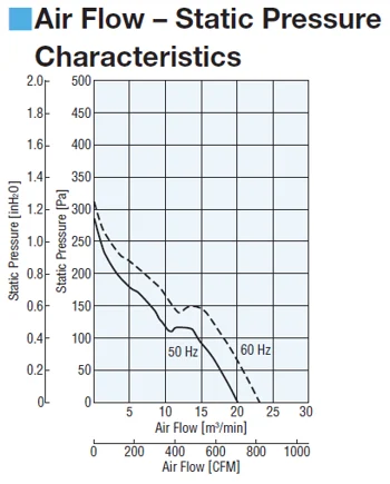
Similar to a motor's speed-torque curve, this graph is how manufacturers show the performance of their fans, and where the air flow and static pressure specifications come from.
For some customers, this may look completely foreign. Many customers I've worked with in the past selected fans based on dimensions and airflow. However, a deeper understanding is necessary to determine how the fan will actually perform in real-life scenarios.
In this post, I’ll explain what airflow and static pressure mean, how they relate, and why impedance plays such a crucial role in fan performance.
Airflow vs Static Pressure
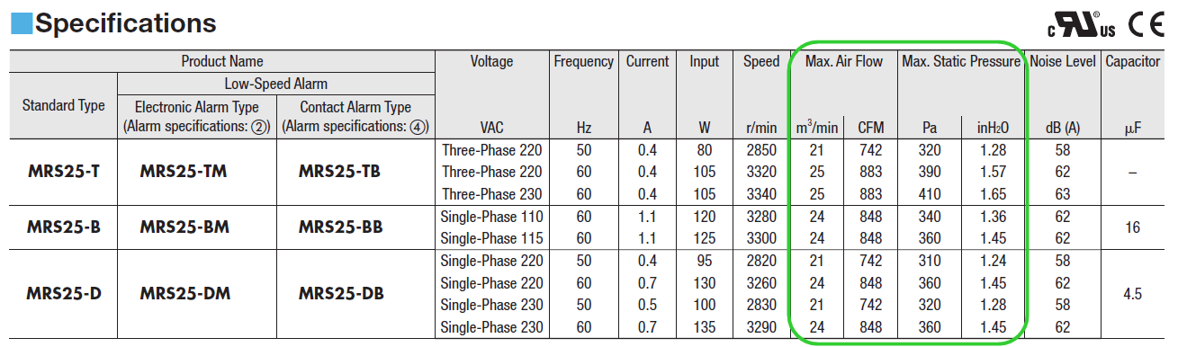
In the above fan specs table, "Max. Air Flow" and "Max. Static Pressure" are listed as key specifications.
Airflow refers to the volume of air that a fan can move over time. It’s measured in cubic meters per minute (m³/min) or cubic feet per minute (CFM). For example, if you have a 5 ft x 5 ft x 5 ft enclosure and a fan that produces 5 CFM, it would take about 25 minutes to fully ventilate the hot air—though in reality, other factors like heat distribution and airflow resistance complicate things.
Static pressure measures the force that a fan can exert to push air through an enclosure. It’s typically measured in Pascals (Pa) or inches of water column (inH₂O). A Pascal is a unit of pressure defined as one newton per square meter, while an inch of water column represents the pressure exerted by a column of water one inch high at standard conditions.
It’s important to note that a fan cannot deliver both maximum airflow and maximum static pressure simultaneously. As one increases, the other decreases due to the nature of the fan’s performance curve.
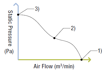
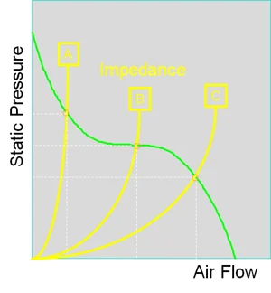
The relationship between airflow and static pressure is shown in the graph above. As airflow increases, static pressure decreases, and vice versa. The three points represent different operating scenarios for the fan.
To visualize these, imagine an electronics enclosure being cooled by a fan. In example 1, the enclosure is open on one side, allowing maximum airflow but no static pressure. In example 3, the enclosure is completely sealed, leading to high static pressure but no airflow. Example 2 is the most common real-world scenario, where the fan encounters some resistance, resulting in a balance between airflow and static pressure.
Â
Installation Density
Now that we’ve covered airflow and static pressure using an electronics enclosure as an example, let’s make it more realistic. An electronics enclosure houses critical components like PLCs, power supplies, and motion control drivers. These generate heat, so a fan is essential to keep temperatures under control. The number of components inside determines the "installation density."
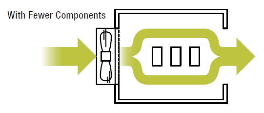
With fewer components (low installation density), there's more space for air to flow, which is similar to example 1, where airflow is high and static pressure is low.
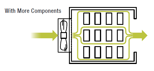
With more components (high installation density), there are more obstructions, reducing airflow and increasing static pressure—similar to example 2.
Â
The Importance of Impedance
How do you determine the actual airflow and static pressure requirements? The answer lies in impedance. Impedance is the resistance to airflow caused by components, walls, or any obstruction in the path of the air. It directly affects the fan’s performance.
For forced air cooling applications, impedance is often calculated using the “square law,†meaning static pressure changes as a function of airflow. The formula is:
P = K × Ï Ã— Qn
Where:
- P = Static pressure
- K = Load factor
- Ï = Fluid density
- Q = Airflow
- n = Constant (typically 2 for turbulent systems)
In the graph below, three yellow lines represent different levels of impedance (A, B, and C). The green line shows the fan’s performance. The actual airflow and static pressure are determined where the impedance curve intersects the performance curve.
Sometimes, determining system impedance can be challenging. In such cases, it’s safe to assume that the actual airflow will be about half of the fan’s maximum. Therefore, selecting a fan that can provide double the required airflow is a good practice.
When designing an enclosure for ventilation, consider not just the fan selection but also the size and placement of intake/exhaust holes, component layout, and airflow patterns. In the video below, smoke is used to demonstrate how different enclosure designs affect airflow, including the impact of varying intake hole sizes and the use of dividers.
Â
Â
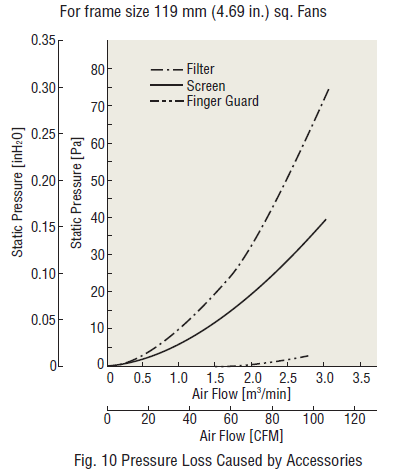
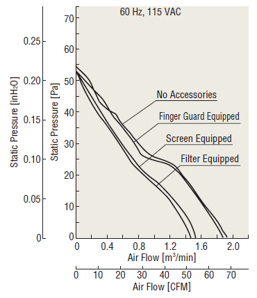
Accessories like filters, screens, or finger guards can improve fan reliability in dusty or wet environments, but they also increase impedance, affecting airflow and static pressure. The graphs below illustrate the pressure loss caused by these accessories.
 |
|
| The above graph shows data regarding pressure loss caused by fan accessories for a frame size 119 mm (4.69") fan. The filter causes the most significant pressure loss, while the finger guard causes little loss. | The above graph shows how characteristics may change with installation of accessories while using the MU1225S-21 fan as an example. Greater pressure loss causes greater reduction of air flow and static pressure characteristics. |
Â
 hbspt.cta._relativeUrls=true;hbspt.cta.load(2284573, '6cb4d806-2dc1-41dd-98df-1b6ae9c2ef6e', {"useNewLoader":"true","region":"na1"});
|
To learn more about fans, please refer to our Topics include:Â
|

Â
CAS 7398-69-8 DADMAC And DMDAAC
Dmdaac For Water Treatment,Dadmac For Cosmetic Industry,Dadmac For Paper-Making Industry,Best Cas 7398-69-8 Dadmac And Dmdaac
ZHEJIANG XINHAITIAN BIO-TECHNOLOGY CO.,LTD. , https://www.dadmacxht.com